
|
| data_mine |
|
|||
|
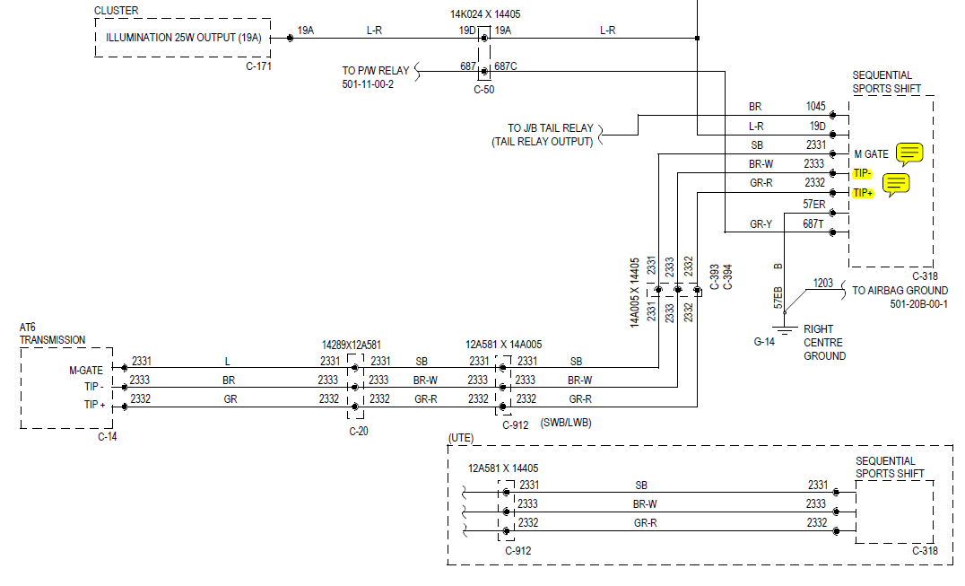
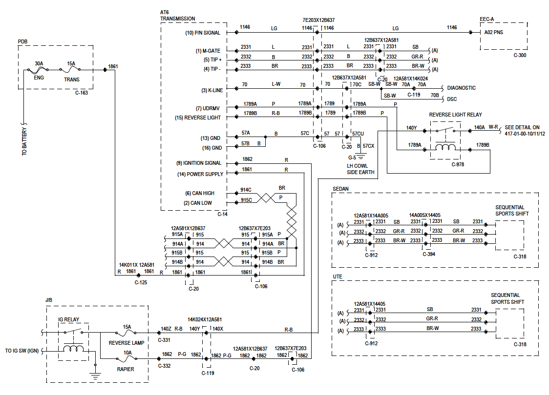
{USERNAME} wrote: {USERNAME} wrote: Straight into the trans. Point me to a circuit diagram? All ZF 6HP26s I ever met don't do that. They're CAN. And the flappy paddles... wired straight in as well?   As for my paddles, I tap into the wires as they come out of the shifter module.
_________________ 1998 DL LTD in Sparkling Burgundy, daily, 302W, stereo, slow |
|||
| Top | |
|||
| fordsme |
|
||
|
{USERNAME} wrote: As for my paddles, I tap into the wires as they come out of the shifter module. Thanks for the excerpts. They don't show much so is the rest online or downloadable somewhere please? |
||
| Top | |
||
| data_mine |
|
|||
|
No they're not available online (try opening the pics in a new window FordMods insist on downsizing them so they're unreadable).
But those diagrams cover everything going to the ZF. The CAN signal goes off to the PCM.
_________________ 1998 DL LTD in Sparkling Burgundy, daily, 302W, stereo, slow |
|||
| Top | |
|||
| fordsme |
|
||
|
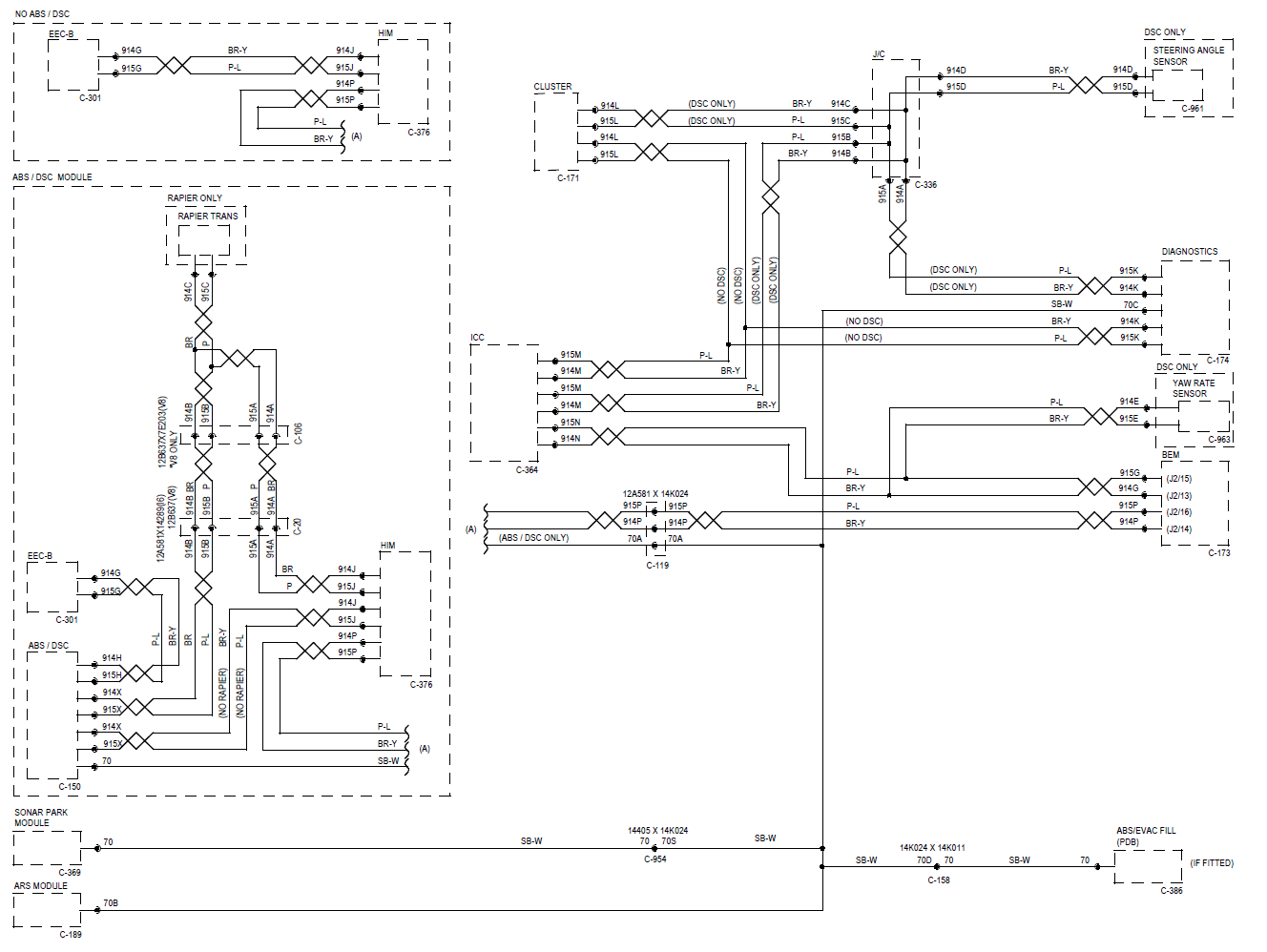
{USERNAME} wrote: No they're not available online (try opening the pics in a new window FordMods insist on downsizing them so they're unreadable). But those diagrams cover everything going to the ZF. The CAN signal goes off to the PCM. Did that immediately, thanks, and can read the pics fine - good size & resolution - just kinda tantalising as they hint at more. Any idea what the OBD module address is for that block described as "AT6 TRANSMISSION" across the K-Line (ISO9141-2)? Do you have a Module Communications diagram or Module Network diagram or the like, showing all the diagnostics networks (buses)? It may be in several parts (for CAN, for ISO, for PWM if any, etc, and should show the DLC - the OBD connector). The EEC-A A02 PNS is as shown on BFpins_a.jpg on AFF I reckon. Sound right? I'll have a hunt round the other diagrams on AFFwhen I get a chance. I don't think this will be on TIS, or is it? |
||
| Top | |
||
| data_mine |
|
|||
|
{USERNAME} wrote: Any idea what the OBD module address is for that block described as "AT6 TRANSMISSION" across the K-Line (ISO9141-2)? Do you have a Module Communications diagram or Module Network diagram or the like, showing all the diagnostics networks (buses)? It may be in several parts (for CAN, for ISO, for PWM if any, etc, and should show the DLC - the OBD connector). The EEC-A A02 PNS is as shown on BFpins_a.jpg on AFF I reckon. Sound right? I'll have a hunt round the other diagrams on AFFwhen I get a chance. I don't think this will be on TIS, or is it? Luke indicates the TCM is 7E1, I haven't verified, but he's usually right on these things. I haven't done it yet, but I assume setting up a 'RT E1' command will give me all the broadcasts sent by the TCM. Module Comms Network, shows CAN and ISO (that's all we have AFIAK)  Yes, that is the PNS signal direct from the PCM (EEC-A connector).
_________________ 1998 DL LTD in Sparkling Burgundy, daily, 302W, stereo, slow |
|||
| Top | |
|||
| fordsme |
|
||
|
{USERNAME} wrote: Luke indicates the TCM is 7E1, I haven't verified, but he's usually right on these things. I haven't done it yet, but I assume setting up a 'RT E1' command will give me all the broadcasts sent by the TCM. Module Comms Network, shows CAN and ISO (that's all we have AFIAK) Hey, thanks! It'll be 7E1 on CAN but it can only be a 2-hex char addr on ISO. (It's unlikely to bear any relationship to the 7e1.) Oh dear! That's a terrible diagram. I can read it fine, but it's very short on detail!! I suspect C-174 is the DLC. And 70C may be the ISO K-line on pin 7. |
||
| Top | |
||
| data_mine |
|
|||
|
{USERNAME} wrote: I suspect C-174 is the DLC. And 70C may be the ISO K-line on pin 7. Yep and Yep.
_________________ 1998 DL LTD in Sparkling Burgundy, daily, 302W, stereo, slow |
|||
| Top | |
|||
| fordsme |
|
||
|
{USERNAME} wrote: I suspect C-174 is the DLC. And 70C may be the ISO K-line on pin 7. {USERNAME} wrote: Yep and Yep. I love the way that Module Comms diagram is wrong!! At least they left off that ISO diag line to the trans module. It's clearly shown on C-14. Is M-GATE what they call the manual shifter for the ZF (I think you have such a thing but am not sure)? And is C-14 on the side (or top or bottom) of the actual ZF case? Know of any pics? |
||
| Top | |
||
| data_mine |
|
|||
|
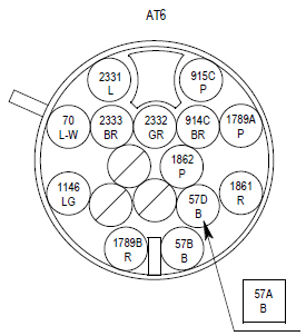
{USERNAME} wrote: {USERNAME} wrote: I suspect C-174 is the DLC. And 70C may be the ISO K-line on pin 7. {USERNAME} wrote: Yep and Yep. I love the way that Module Comms diagram is wrong!! At least they left off that ISO diag line to the trans module. It's clearly shown on C-14. Is M-GATE what they call the manual shifter for the ZF (I think you have such a thing but am not sure)? And is C-14 on the side (or top or bottom) of the actual ZF case? Know of any pics? The diagrams is what we've got to deal with. M-GATE goes low when the shifter is moved 'over to the left' to enable 'performance mode' (Dperf - if you leave it alone), or manual mode (push it forward or back, which sends low TIP- and TIP+ respectively). The box ignores TIP- and TIP+ if M-GATE isn't low. Which for me is handy, because while the shifter can't be accidentally moved when it's not over to the left, my paddles can be, the box happily ignores them if the shifter is in D or any other position. C14 is on the box, it's a round mutlipin plug (kind of like a DIN style but bigger). Don't have a picture handy now (at work).
_________________ 1998 DL LTD in Sparkling Burgundy, daily, 302W, stereo, slow |
|||
| Top | |
|||
| fordsme |
|
||
|
{USERNAME} wrote: M-GATE goes low when the shifter is moved 'over to the left' to enable 'performance mode' (Dperf - if you leave it alone), or manual mode (push it forward or back, which sends low TIP- and TIP+ respectively). The box ignores TIP- and TIP+ if M-GATE isn't low. Which for me is handy, because while the shifter can't be accidentally moved when it's not over to the left, my paddles can be, the box happily ignores them if the shifter is in D or any other position. C14 is on the box, it's a round mutlipin plug (kind of like a DIN style but bigger). Don't have a picture handy now (at work). Thanks! I'd be grateful for pics of that connector. The ZF in your car is a very interesting variant of the ones I've met before. |
||
| Top | |
||
| data_mine |
|
|||
|
 Not an actual pic, but the connector layout. The circuit numbers will match up the the diagrams previously posted.
_________________ 1998 DL LTD in Sparkling Burgundy, daily, 302W, stereo, slow |
|||
| Top | |
|||
| fordsme |
|
||
|
{USERNAME} wrote:  Not an actual pic, but the connector layout. The circuit numbers will match up the the diagrams previously posted. Brilliant! Thank you. Looks very like the one I have but the diagram for mine doesn't list some of those pins at all. Now to hunt for more data on the actual network messages on the Falcons... |
||
| Top | |
||
| data_mine |
|
|||
|
{USERNAME} wrote: {USERNAME} wrote:  Not an actual pic, but the connector layout. The circuit numbers will match up the the diagrams previously posted. Brilliant! Thank you. Looks very like the one I have but the diagram for mine doesn't list some of those pins at all. Now to hunt for more data on the actual network messages on the Falcons... I've found some doco that shows ZF make two electronics (TCM) modules, one (M spec - the one we have) has three extra wires, for control of the shifting, the other (E spec) relies on CAN messages to do so, and is missing those three wires.
_________________ 1998 DL LTD in Sparkling Burgundy, daily, 302W, stereo, slow |
|||
| Top | |
|||
| fordsme |
|
||
|
{USERNAME} wrote: I've found some doco that shows ZF make two electronics (TCM) modules, one (M spec - the one we have) has three extra wires, for control of the shifting, the other (E spec) relies on CAN messages to do so, and is missing those three wires. Oh Is that somewhere I can see it please? BTW, page 3 of http://www.thectsc.com/images/pdf/6_spe ... cement.pdf shows the connector whose pic you posted - thanks for helping me find it. You may like more of the doc on http://www.thectsc.com/index.php?p=page ... =tech_info When you mention "M spec" and "E spec" are these the same as the M-shift and E-shift in http://www.thectsc.com/images/pdf/thect ... cement.pdf ? |
||
| Top | |
||
| data_mine |
|
|||
|
{USERNAME} wrote: {USERNAME} wrote: I've found some doco that shows ZF make two electronics (TCM) modules, one (M spec - the one we have) has three extra wires, for control of the shifting, the other (E spec) relies on CAN messages to do so, and is missing those three wires. Oh Is that somewhere I can see it please? BTW, page 3 of http://www.thectsc.com/images/pdf/6_spe ... cement.pdf shows the connector whose pic you posted - thanks for helping me find it. You may like more of the doc on http://www.thectsc.com/index.php?p=page ... =tech_info When you mention "M spec" and "E spec" are these the same as the M-shift and E-shift in http://www.thectsc.com/images/pdf/thect ... cement.pdf ? Page 12/13 http://www.scribd.com/doc/24267127/Audi ... 6%E2%80%9D yeah, replace spec with shift. I remembered incorrectly.
_________________ 1998 DL LTD in Sparkling Burgundy, daily, 302W, stereo, slow |
|||
| Top | |
|||
| Who is online |
|---|
Users browsing this forum: No registered users and 9 guests |