
|
| sly |
|
||
|
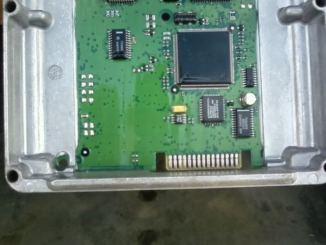
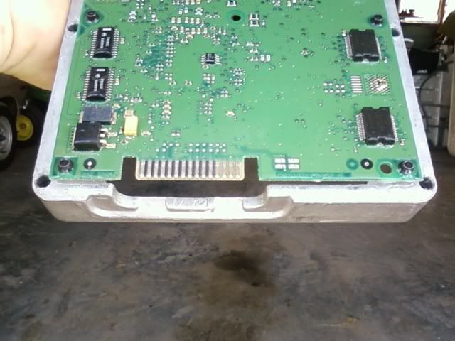
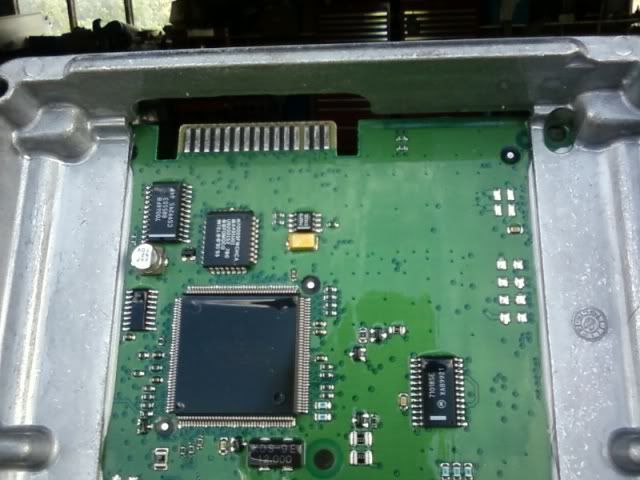
The subject says it all, really. Check out the pix, this is an AU1 PCM which apparently needs the solder pads near the J3 connector joined horizontally with wires to allow a J3 to function properly. The car this PCM came from had a cam & chip combo years ago - the car used to go totally autistic & refuse to start every few weeks, requiring a tow to a workshop and reflash of the ECU with a $$$cantool. I don't believe the pads have been joined or have the little black resistors on the reverse side, but then I'm no expert on this. Can someone who knows their s**t check these out & tell me if my suspicions are right?
  
_________________ AU1.5 Wagon, Raptor ProStreet kit, Pacemaker 4499's with 3" collector, 3" metal cat, 3" pipe, Pex BSO660 & BSO439, BA brakes, Sprintgas mixer LPG system, Airod variable-venturi mixer... stealth FTW Sniper tuned! |
||
| Top | |
||
| data_mine |
|
|||
|
Need better (bigger) pics.
But you shouldn't need to make any electrical modifications to the ECU. Just ensure all the water proofing goo is removed from the J3 connector. So you get a good connection to the chip. Some people recommended a light sanding, I just spent a lot of time cleaning the connector with a plastic edge (the black plastic cover, to be exact).
_________________ 1998 DL LTD in Sparkling Burgundy, daily, 302W, stereo, slow |
|||
| Top | |
|||
| SLO247 |
|
||
|
{USERNAME} wrote: Need better (bigger) pics. But you shouldn't need to make any electrical modifications to the ECU. Just ensure all the water proofing goo is removed from the J3 connector. So you get a good connection to the chip. Some people recommended a light sanding, I just spent a lot of time cleaning the connector with a plastic edge (the black plastic cover, to be exact). The instructions for the TI Performance J3 specify that what the OP is talking about, is completely necessary. E-Series units need no modification. He is working with an AU item though. |
||
| Top | |
||
| data_mine |
|
|||
|
{USERNAME} wrote: {USERNAME} wrote: Need better (bigger) pics. But you shouldn't need to make any electrical modifications to the ECU. Just ensure all the water proofing goo is removed from the J3 connector. So you get a good connection to the chip. Some people recommended a light sanding, I just spent a lot of time cleaning the connector with a plastic edge (the black plastic cover, to be exact). The instructions for the TI Performance J3 specify that what the OP is talking about, is completely necessary. E-Series units need no modification. He is working with an AU item though. Fair enough, I never played with AU ECU's.
_________________ 1998 DL LTD in Sparkling Burgundy, daily, 302W, stereo, slow |
|||
| Top | |
|||
| sly |
|
||
|
{USERNAME} wrote: Need better (bigger) pics. Sorry, that's the best I can get with my mo-pho. They are IMHO at least as good as the pix on the TI Performance website but. I can try with a better camera if it's too hard to tell. There's a Fuji S1600 lying around here somewhere, but despite 15x optical zoom it doesn't really do macro mode. Close-ups just blur so I'm not confident of getting better. The connections are to the left of the J3 connector in the first photo, and to the right in the 2nd and 3rd. Apparently soldering is only required on Series 1 AU's, not on earlier or later cars. I suspect the workshop that did the job were also unaware of this. They've long since gone bankrupt...
_________________ AU1.5 Wagon, Raptor ProStreet kit, Pacemaker 4499's with 3" collector, 3" metal cat, 3" pipe, Pex BSO660 & BSO439, BA brakes, Sprintgas mixer LPG system, Airod variable-venturi mixer... stealth FTW Sniper tuned! |
||
| Top | |
||
| galapogos01 |
|
|||
Posts: 1139 Joined: 27th Feb 2005 Ride: Supercharged EF Fairmont Location: T.I. Performance HQ |
I thought my pics were OK if you zoomed in, but the PDF has compressed them... will try to update... anyway, this pic:
 Seems to indicate you have the black resistors, so you don't need to solder. Your J3 port, however, appears a bit gungy. Might want to give it a going over as per the guide or data_mine's instructions. ps: To take better macro pics, use macro mode, zoom about 1/2 way (no digital zoom), and ensure you are a good 30-40cm away from the surface of the ECU. Take the pic in the highest res possible then crop it up.
_________________ {DESCRIPTION} - {DESCRIPTION}, {DESCRIPTION}, {DESCRIPTION}, {DESCRIPTION} and more! |
|||
| Top | |
|||
| sly |
|
||
|
{USERNAME} wrote: this pic: <snip> Seems to indicate you have the black resistors, so you don't need to solder. Your J3 port, however, appears a bit gungy. Might want to give it a going over as per the guide or data_mine's instructions. I can't even see the black resistors looking at the board in bright daylight. They must be bloody small. So the J3 port is dirty, that's no surprise considering the workshop that did the job has since gone bankrupt. But again, I can't really tell. What looks to be wrong with it?
_________________ AU1.5 Wagon, Raptor ProStreet kit, Pacemaker 4499's with 3" collector, 3" metal cat, 3" pipe, Pex BSO660 & BSO439, BA brakes, Sprintgas mixer LPG system, Airod variable-venturi mixer... stealth FTW Sniper tuned! |
||
| Top | |
||
| galapogos01 |
|
|||
Posts: 1139 Joined: 27th Feb 2005 Ride: Supercharged EF Fairmont Location: T.I. Performance HQ |
Read zis:
http://www.tiperformance.com.au/Technic ... 20Chip.pdf Jase
_________________ {DESCRIPTION} - {DESCRIPTION}, {DESCRIPTION}, {DESCRIPTION}, {DESCRIPTION} and more! |
|||
| Top | |
|||
| Futuraclassic |
|
||
|
hey mate i have a au fairmont series 1 and i had a chip that i had to solder for. only in au series 1's though. i think i have a pic some where but i may have deleted it. but check out that link to tiperperformance cos it shows u which ones to do.
_________________ People hate the au series but i wouldnt have it any other way!!! |
||
| Top | |
||
| Who is online |
|---|
Users browsing this forum: No registered users and 84 guests |