

|
| FAST-XR |
|
|||
|
the angle of the merge will have to be increased in order to shorten it, up to 25-30 degrees is seems to be acceptable...
_________________ 07 BF MKII XR6T |
|||
| Top | |
|||
| krisisdog |
|
|||
|
Yeh I realise that, but it seems like a mighty easy way to lower it without effecting performance or ruining the lengths of the runners..
|
|||
| Top | |
|||
| dsyfer |
|
|||
|
The problem with shortening the collector, like Fast XR said is the angle of the pipes change, which will then change all the primary pipes. But it also changes how the exhaust gases enter the turbo, using 15 degrees gives a pretty straight run but still allows access to properly weld the collector. Currently it is as short as it can be without compromising the strength.
|
|||
| Top | |
|||
| FAST-XR |
|
|||
|
i looked into merge design a while back, 25 degrees is still an ideal merge, 30+degrees is not...
_________________ 07 BF MKII XR6T |
|||
| Top | |
|||
| dsyfer |
|
|||
|
That's good to know that you can go up to 25 degrees.
Been thinking about a jig for cutting the collector pipes, the simplist way i can think of is: Triangular base plate at 60 degrees angles, which will serve as a guide for the bandsaw, angle iron at 15 degrees will allow me to clamp work to the angle iron. 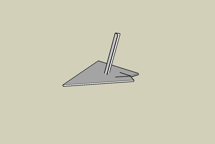 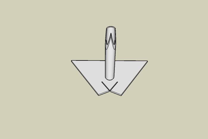 
|
|||
| Top | |
|||
| FAST-XR |
|
||||||
|
another option without creating a jig;
since your using CAD, you should be able to project a curve, print it out 1:1 and trace it onto the tube by hand
_________________ 07 BF MKII XR6T |
||||||
| Top | |
||||||
| Dansedgli |
|
||
|
I took my manifold off today and thought these pics might help you. My flange sits a fair bit lower than yours looks and the flange is on an angle to point the compressor inlet to the corner of the car.
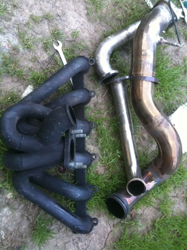 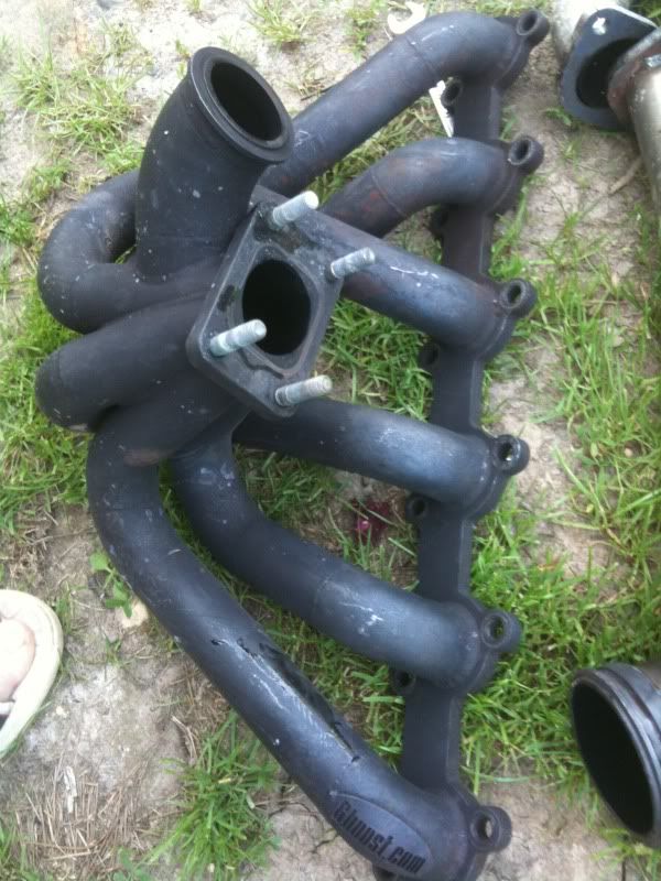 Heres a better pic showing the flange position. 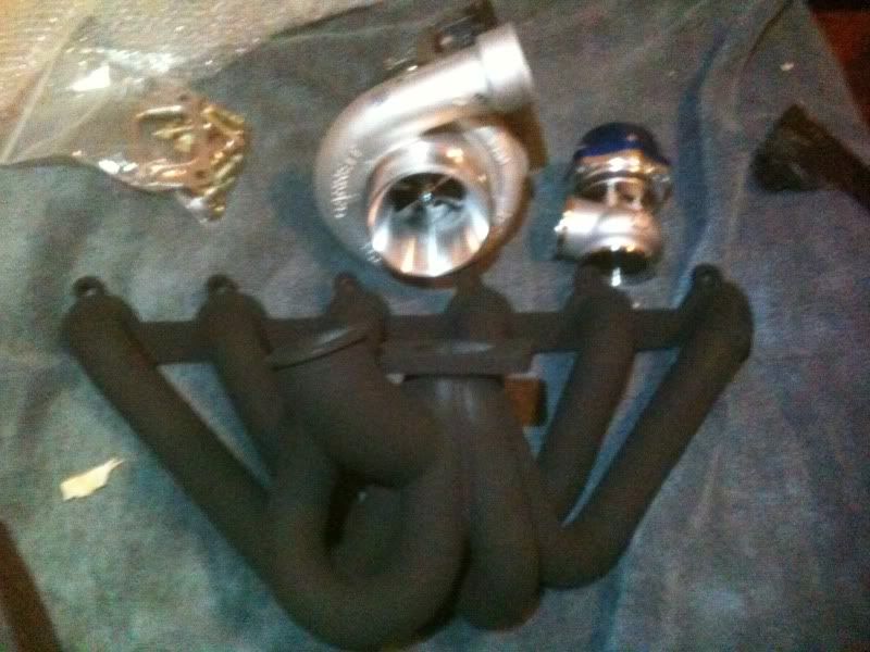
|
||
| Top | |
||
| dsyfer |
|
|||
|
{USERNAME} wrote: another option without creating a jig; since your using CAD, you should be able to project a curve, print it out 1:1 and trace it onto the tube by hand That was the original idea, but if I am going to make one I want to do a few, so I am hoping the jig may be quicker. |
|||
| Top | |
|||
| dsyfer |
|
|||
|
{USERNAME} wrote: I took my manifold off today and thought these pics might help you. My flange sits a fair bit lower than yours looks and the flange is on an angle to point the compressor inlet to the corner of the car.   Heres a better pic showing the flange position.  Cheers for that Dan, what sort of clearance do you have between the bonnet and the turbo housing? Does angling towards the corner make it harder to fit a dump? |
|||
| Top | |
|||
| dsyfer |
|
|||
|
I made some new ram tubes for an experiment at tomorrow's dyno day, keeping them longer and not as open I am trying to get an increased air speed, on the road they are a big improvement over the originals, better mid/top than the plenum, but not as much low/mid as the plenum.
It's amazing the difference shaping the air a little does. 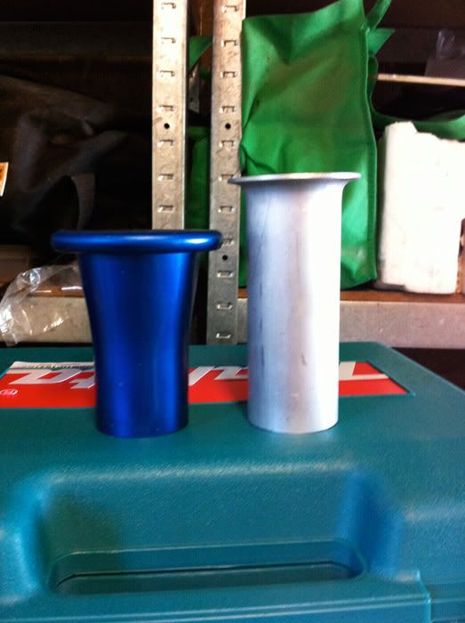 As long as I can go in the engine bay. 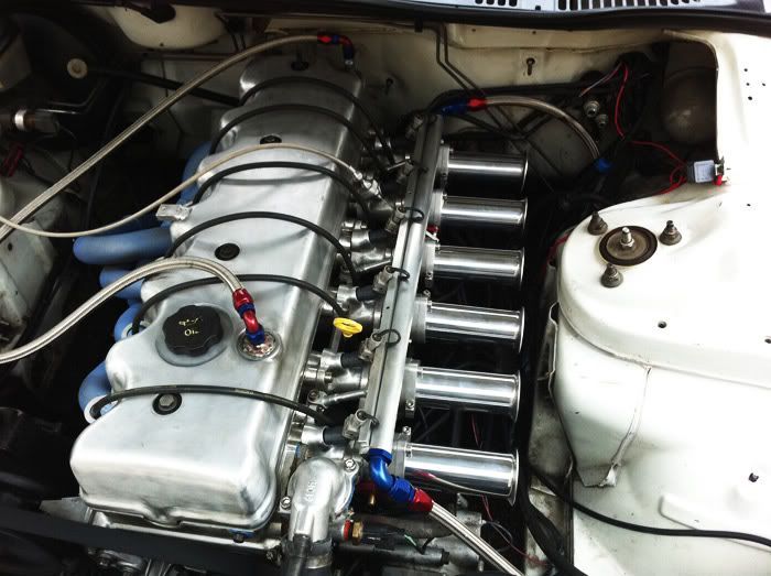 I have been working on trying to fine tune the drivability of the tune, due to the nature of the ITB's having such a big surface area for small throttle openings it's hard to get a reasonable idle and cruise AFR, without either leaning out under throttle or richening up at idle. I found by taking a fair bit of fuel out with the "fuel override" using vacuum gives a good idle and cruise but not good acceleration, eventually by playing with all three "TPS, Fuel override & accel enrichment" I have got a pretty good drivable tune, I ended up with a 50% throttle enrichment to get a nice clean response, 15-20% is normal with a single TB. |
|||
| Top | |
|||
| Dansedgli |
|
||
|
There is heaps of clearance under the bonnet.
The housing doesnt sit very far above the rocker cover. The dump pipe is harder to make because you need to add a bend in but there is still a lot of room. This makes fitting a 4 inch pipe on the intake easier though. I could go up to 3.5 - 4 inch dump I think provided the dump is sheilded from the spark leads. It gets pretty close to number 5. You can sort of see how it relates to the rocker cover here: http://i140.photobucket.com/albums/r3/d ... /008-1.jpg Spark lead clearance here: http://i140.photobucket.com/albums/r3/d ... G_0340.jpg |
||
| Top | |
||
| Jeremy BA |
|
|||
Age: 51 Posts: 85 Joined: 10th Nov 2010 Ride: Ford BA FUTURA 2002Ded Gas Wagon Location: FRANKSTON |
You're going about this all wrong. Imagine the awesomeness
Anyway mate you have some serious Fab skills there great work i look forward to seeing the finished product.
_________________ I'm constantly surrounded by IDIOTS!! |
|||
| Top | |
|||
| dsyfer |
|
|||
|
{USERNAME} wrote: You're going about this all wrong. Imagine the awesomeness Anyway mate you have some serious Fab skills there great work i look forward to seeing the finished product. How about six of these into six little intercoolers into six little plenums into six throttle bodies?? IHI RHB31 3T-505 Worlds Smallest Turbocharger 
|
|||
| Top | |
|||
| 4LEDboy |
|
|||
|
I want one, its cute!
_________________ {DESCRIPTION} < Click on it! You know you want too! Quote: Thats not the point *a**hole
|
|||
| Top | |
|||
| TROYMAN |
|
||
|
i thought the gt20 i have in my shed for my motorbike was small...lol
|
||
| Top | |
||
| Who is online |
|---|
Users browsing this forum: Google [Bot] and 98 guests |