

|
| BF XR |
|
||
|
get rid of the GLi badge
theres a hole under the falcon but if u peel off the GLi and fold it up onto the falcon it will snap off from the bottom of the falcon badge. then just remove the rest of the tape otherwise looking good |
||
| Top | |
||
| || xXFalconXx || |
|
|||
|
looks great man keep it up
_________________ PH4490 Pacemaker Headers |
|||
| Top | |
|||
| Vic |
|
|||
|
Don't forget to change all the dectronooter valves.
_________________ 5.6L of carbon footprint. |
|||
| Top | |
|||
| asizzy |
|
||
|
{USERNAME} wrote: Don't forget to change all the dectronooter valves. wtf is that?
_________________ AsIzZy |
||
| Top | |
||
| Vic |
|
|||
|
They're in the return cycle system, sometimes they get jammed so it's best to swap them out.
_________________ 5.6L of carbon footprint. |
|||
| Top | |
|||
| asizzy |
|
||
|
{USERNAME} wrote: They're in the return cycle system, sometimes they get jammed so it's best to swap them out. Cannot compute!
_________________ AsIzZy |
||
| Top | |
||
| fiend |
|
|||
|
Try Googling it. "dectronooter"
|
|||
| Top | |
|||
| asizzy |
|
||
|
Just comes up with my thread.
_________________ AsIzZy |
||
| Top | |
||
| comhelp |
|
||
Age: 41 Posts: 638 Joined: 6th Nov 2004 Ride: 1994 Ford EF Fairmont Ghia Sedan Location: Melbourne |
{USERNAME} wrote: Don't forget to change all the dectronooter valves. I told you to stop posting after you have been drinking vic
_________________ 1994 ford fairmont ghia - Currently 302 with T5 - Work in progress |
||
| Top | |
||
| Vic |
|
|||
|
I might be spelling it wrong but they work in conjunction with the powerband adjustment and are pre-calibrated.
_________________ 5.6L of carbon footprint. |
|||
| Top | |
|||
| comhelp |
|
||
Age: 41 Posts: 638 Joined: 6th Nov 2004 Ride: 1994 Ford EF Fairmont Ghia Sedan Location: Melbourne |
where excatly are you talking about that these are located? I may be able to find out some more info on them
_________________ 1994 ford fairmont ghia - Currently 302 with T5 - Work in progress |
||
| Top | |
||
| asizzy |
|
||
|
{USERNAME} wrote: I might be spelling it wrong but they work in conjunction with the powerband adjustment and are pre-calibrated.
_________________ AsIzZy |
||
| Top | |
||
| Vic |
|
|||
|
IIRC, slick had a similar fault.
_________________ 5.6L of carbon footprint. |
|||
| Top | |
|||
| asizzy |
|
||
|
{USERNAME} wrote: IIRC, slick had a similar fault. Man, I still don't know what your on about...... Don't mean to be rude but can you explain in poor mans English.
_________________ AsIzZy |
||
| Top | |
||
| asizzy |
|
||
|
Ok, got time to add what i've done to the car now. I'll narrate what i did and add the pickies later.
So first up following this thread to begin with: ford-audio-visual-f5/reverse-sensor-mod-on-ef-t83483.html?hilit=reverse%20sensors I sorted out the electrical components i needed: 1x Horn Relay Base {DESCRIPTION} 1x 30A Horn Relay - SPDT {DESCRIPTION} 1x Sensor kit (Mazda kit) First started thinking where will i get my power source from??? Thought about getting it from the ciggy then i looked in the boot what do you know i have a power distribution block with two spare points... bingo. Got the power all set now to think about if im going to use a relay i need a trigger and reverse sensor well the reverse tail light wire should do for this. I mounted the Module that came with the kit behind the bracket for the amp's factory place. Also mounted the relay base and connected up the wires accordingly to the pic. 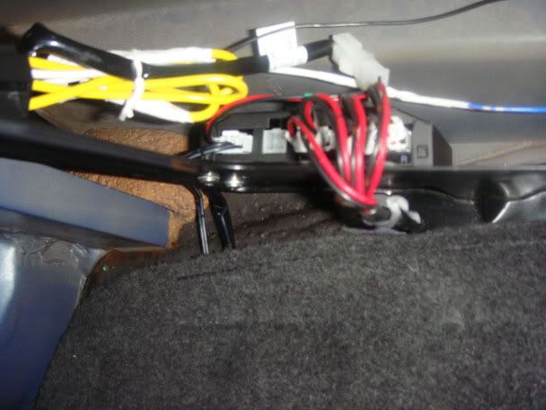 Then where should the beeper go??? leave it in the boot hmmm looked under the steering column and found the perfect place. So had to take the rear seats out to run the cable along the side and under the carpet and behind the kick panel and behind the fuse block. 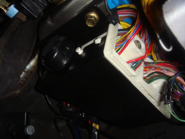 And whats next oh yeah... need to cut holes on the bumper time. Didnt really take pictures when i drilled the holes but you get the idea. Holes cut sensors in, some silicone at the back to hold it sturdy. Took a long time ti think where i will drill the holes, firstly identified the middle point on the bumper and worked from there. Didnt want the sensors so much to the corners of the bumper but where its a bit straight. Also had to take into consideration that i had two flush based sensors and two elevated and in a bit of an angle sensors as seen on the pictures. While drilling the holes made a bit of a boobo. 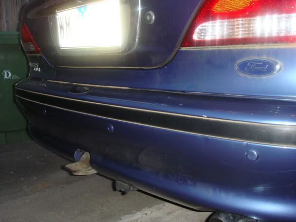 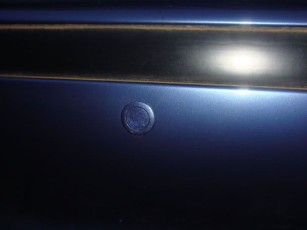 Run the cabling behind the bumper and cable tied it so to avoid any future dramas and cut a small hole in one of the plugs as you can see in the picture and put the cable through that point to inside the boot and plugs into the module behind the amp bracket at least its now used for something haha. 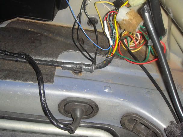 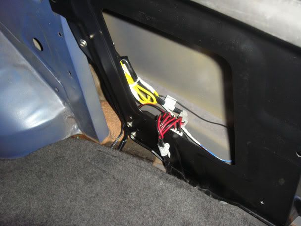 And also forgot to mention that the sensors was in different colours and had to sand it back and repaint to my car colour
_________________ AsIzZy Last edited by asizzy on Tue Nov 17, 2009 10:43 pm, edited 1 time in total. |
||
| Top | |
||
| Who is online |
|---|
Users browsing this forum: No registered users and 11 guests |