

|
| TimmyA |
|
|||
|
really?
I thought they blow a big hole in the pad? The BA one has weak points through it where its designed to "tear" Don't have an AU clock spring (6 wire) you'll sell me Ash? the two mating plugs from under the dash and the switches (just for the plugs, don't need to be in good nic or even working)? Cheers, Tim
_________________ {DESCRIPTION} |
|||
| Top | |
|||
| TimmyA |
|
|||
|
AUI may only have a 5 clock spring I'm thinking... :/ I want a 6 wire one this time just in case I need to add another function...
If you can confirm either way I don't mind... AUII I think has the radio buttons and the speed alert thing which gives it 6 wires? Either though mate... Just the 6 wires is paramount Ah ok then... wont work Cheers, Tim
_________________ {DESCRIPTION} |
|||
| Top | |
|||
| TimmyA |
|
|||
|
Sounds good...
Its all there? spring, buttons, two plugs from under dash? Let me know what you want and I'll wire you the green stuff... Cheers, Tim
_________________ {DESCRIPTION} |
|||
| Top | |
|||
| TimmyA |
|
|||
|
Sure do...
Just the two plugs that plug into the clock spring... I'll re-do my clock spring and change the BA plug on the adaptor harness I made to the AU one... That way The clock spring will not be modified this time, just the switches will be... So should I ever go to sell it/upgrade it the switches will plug straight into an AU clock spring and work in an AU (same cruise module)... Guessing the plugs on the clock springs change from EF/EL to AU as to incorporate that extra wire... :/ I'll go this way... If I upgrade in the future and sell it, it can be modified to EF/EL then... :/ I'm just worried about getting it into my car for now... Cheers, Tim
_________________ {DESCRIPTION} |
|||
| Top | |
|||
| TimmyA |
|
|||
|
Cool..
Na matey got no idea... I thinking it'll be the same as the BA wheel in terms of "offset" if you can call it that... The combo switches look strikingly similar is why i think that... Only difference I've noticed the FG combo has the option of having a fog light toggle on the blinker stalk... Something I'd not seen in BA's... Will all be part of the puzzle once I get it and bolt it on... Looking forward to it as I think the FG is a large step over the BA/BF wheel with its greatly reduced air bag pad... Nicer buttons and that... In a weeks time there will no doubt be another massive post of photos and no doubt problems... :/ haha... Its all fun and games hey?
_________________ {DESCRIPTION} |
|||
| Top | |
|||
| TimmyA |
|
|||
|
Ah yes...
For those who can actually follow all the dribble I go on about... :/ Been thinking lately the dash may come back out one day too once I get the Cam in an EL instruments in... Once I have everything working how I want I'll tidy all that wiring up and make it into one loom that runs across the original... I've since added a couple of wires and discovered I've mixed up the data wire for the ED trip computer / EL inst cluster... I would love to get the El trip computer into the car for accuracy reasons... I bought one but it looks to be one almighty impossible task to integrate the EL board into the ED case/screen/buttons... The El inst cluster gives all the trip info once in diag mode anyway... Does anyone know if it stays in the diag mode all the time, needs to be entered into it everytime you start the car, or times out while driving? If/when I go turbo charged one day when its not a daily... Does this trip computer data (L/100km) become invalid when you run larger than std injectors? Not that its probably overly accurate now (they never are)... But just curious on this... All fun and games and always something to tinker with... Soon to get back to work on my house too... Would be nice to make it liveable within the next 12 months... Cheers, Tim
_________________ {DESCRIPTION} |
|||
| Top | |
|||
| TROYMAN |
|
||
|
{USERNAME} wrote: If/when I go turbo charged one day when its not a daily... Does this trip computer data (L/100km) become invalid when you run larger than std injectors? Not that its probably overly accurate now (they never are)... But just curious on this... Cheers, Tim tim once you go away from the std injectors or increase fuel rate the trip comp is totaly pointless... well the fuel usage average and instant are way off... |
||
| Top | |
||
| TimmyA |
|
|||
|
Hi Ash,
Don't need the combo switch... Just the clock spring... And yes the two plugs that are part of the dash loom that plug into the clock spring... And those radio buttons pictured too... Clock spring has 6 wires? Troy... I very well thought this may be the case... Cheers, Tim
_________________ {DESCRIPTION} |
|||
| Top | |
|||
| TimmyA |
|
|||
|
ahhh...
Itsa Nice... Looks good to me... Should be good... Let me know what I owe you and I'll wire the money through... This is the largest part sorted... just to find a airbag now... Cheers, Tim
_________________ {DESCRIPTION} |
|||
| Top | |
|||
| TimmyA |
|
|||
|
I do believe that may be an issue... Usually the wheel gets sold due to an accident resulting in a detonated airbag...
FTG confirmed they destroy the horn pad on detonation like the BA ones... So now the waiting game... I don't even think its worth asking George what a new one is worth...can see them being around the 1k mark new... :/ Cheers, Tim
_________________ {DESCRIPTION} |
|||
| Top | |
|||
| TimmyA |
|
|||
|
Now just to wait and see... :/
And be very shocked...
_________________ {DESCRIPTION} |
|||
| Top | |
|||
| TimmyA |
|
|||
|
Forgot to get back to you Ash...
A whole $505 The goods have arrived... So its been an afternoon of comparing and working out the cruise buttons... Here is some pics... 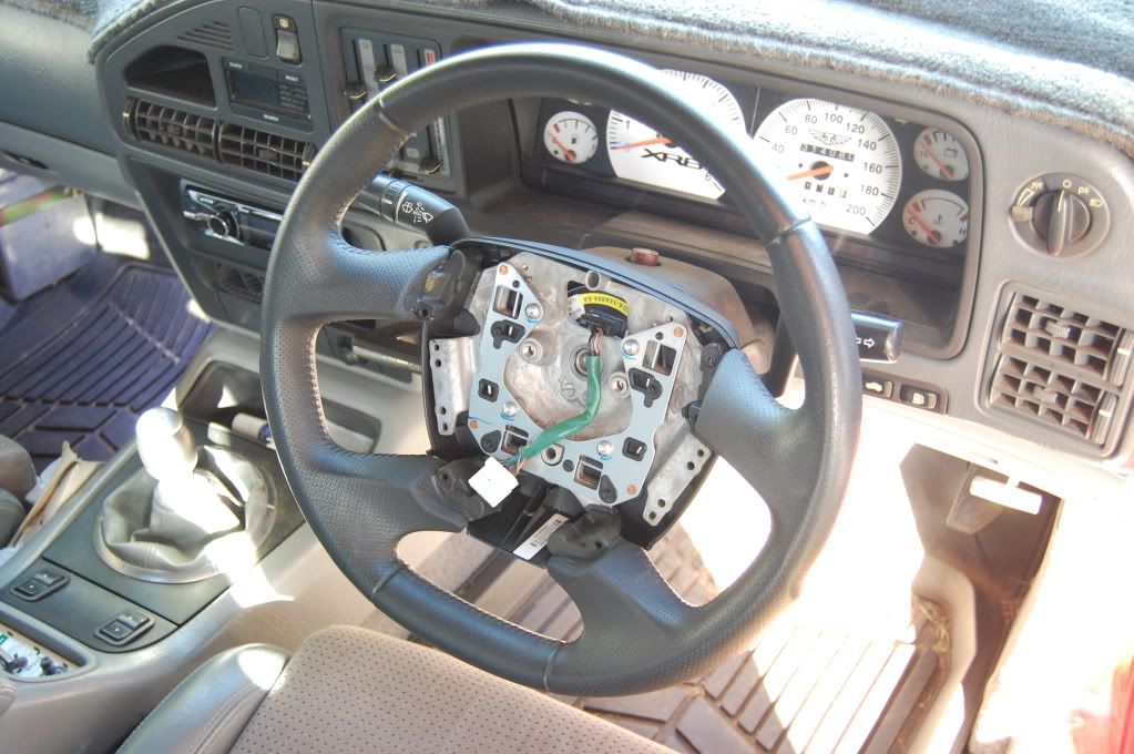 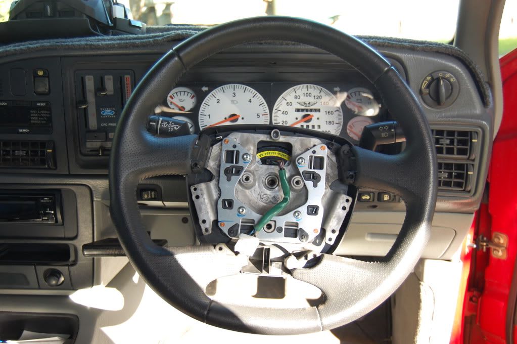 There is an improved clearance to the wiper arm specifically but more to the indicator arm as well... This means that no matter where the wheel is the wiper arm seems to hit no part of the wheel... Which it does on the BA one... So stoked about that... Indicator: 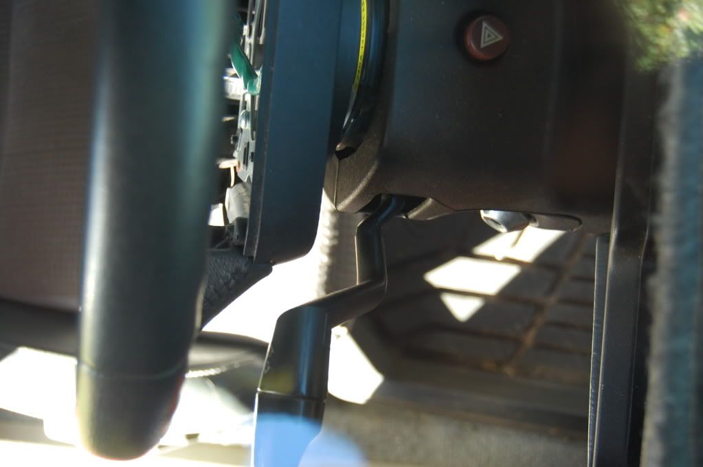 Wiper: 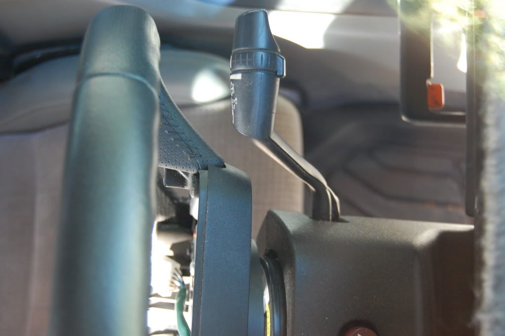 Still got heaps of gap to the plastic cowlings... But I don't see it from where I'm sitting... 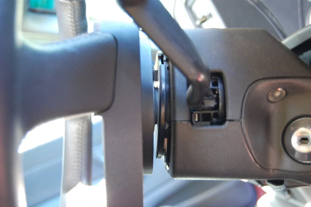 They appear to be very close to the same offset (BA on left FG on right: 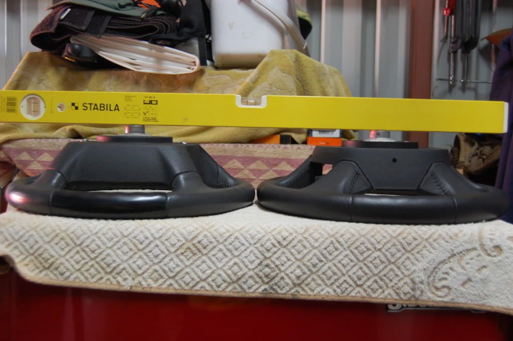 Despite appearing to have a flat bottom it really doesn't deviate that much from the BA wheel shape (BA on bottom FG on top): And here is the cruise buttons circuit board that needs to be re-wired to accommodate the EF/EL cruise module I'm running... I would like to commend Ford for making these so much easier to get apart than the BA ones... however you physically have to remove to the plastic buttons to get the board out... I found there to be an art to this... If you hold your tongue to the left, tilt your head fractionally to the right... And spin to the left with a constant speend of about 20 turns a minute while holding pressure in the right spot with a screw driver you may be able to unclip them 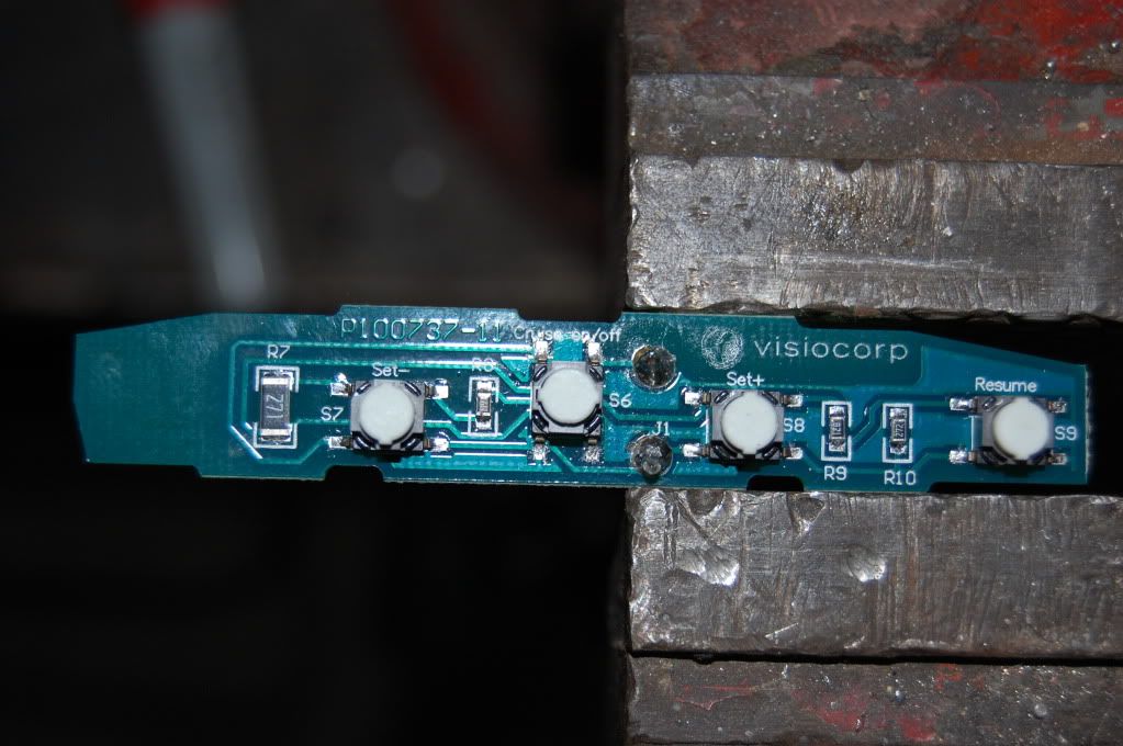 Good news is I can make the blank into a button... I just have to find those buttons for sale somewhere (can see it being a needle in a haystack) and then glue it to the board, and remove the plastic thingo that stops it from being pressed and I have a 4th button on that side... Bad news is my steering puller I made will not work with the FG wheel so I'll have to make a new one... So far really happy... Looks good and fits great... BA owners cannot fit an FG wheel because the radio buttons are completely different resistances (unless you change them all out if possible)... Not sure about the cruise ones though yet... I know they're wrong for what I need plus they're two wire arrangement and I need three... Other good point is they done away with those two stupid screws that hold the airbag on... now there is a hole in the bottom of the back plastic cover and you press a tiny screw driver and it releases it... press to clip back on but the looks... Thoughts as always? Cheers, Tim
_________________ {DESCRIPTION} |
|||
| Top | |
|||
| TimmyA |
|
|||
|
No worries mate...
Cruise buttons modify basically exactly the same way... The cruise buttons I reckon would work on a BA as only on resistor is different and its basically within the 5% tolerance I guess an SMD resistor would have... The radio buttons are massively different... Recap on the BA ones then under it the FG ones 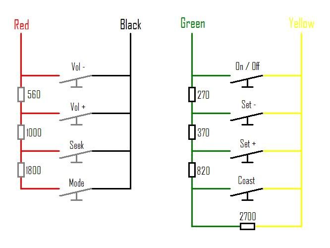 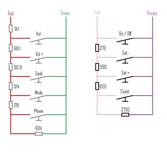 And this is the mod to the cruise side to work with EL cruise 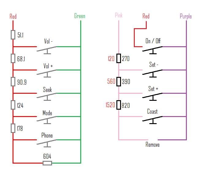 One should note the two red wise are not connected... The red wire for the radio buttons is the sense into the PAC unit I have... The red wire on the cruise is the horn wire colour used in the buttons too... Pink will be send (basically just a ground) out of the cruise module Purple will be receive (sense)... The spare bung in the cruise switches I am considering for one of two things... Option one is to cycle the digital read out in the NL cluster I have to go in... Thats if it will stay in diagnostic mode once you enter into it... The you can cycle while driving to see various info without reaching through the wheel... Other option is as a cruise "off" button, but I may make up the flip flop so the one button works as on and off (something I still haven't found the motivation for...) So thats it for the moment... Done enough study on it for tonight... I know where I stand now... Cheers, Tim
_________________ {DESCRIPTION} |
|||
| Top | |
|||
| TimmyA |
|
|||
|
Successes thus far...
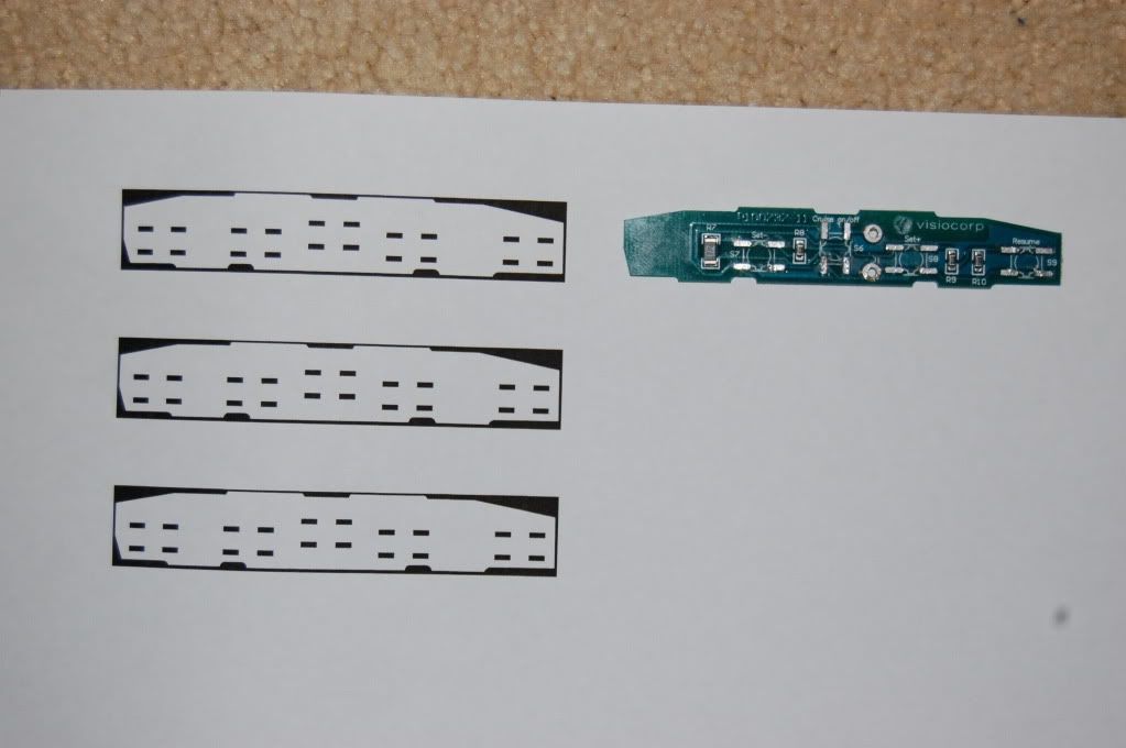 This is what happens when you have a brother fairly handy in photoshop... I desoldered the buttons and scanned the board at high res... Little brother converted the JPEG to that bitmap file which is 1:1 ratio and copied over the copper pads for the buttons to solder to... Measured the radio buttons and replicated the 5th button which is blanked out onto the board... Now I can draw in my own custom tracks and resistor mounts for that professional look... When I have it sorted little bro will draw them into photo shop, reprint, transfer, etch, and finish the board... Also rotate the pads for the mode button by 90 degree,,, makes it much easier to route tracks... I have no idea why Ford put it at 90 degrees than ran tracks for mile around the board... Anyway that stage is progressing... 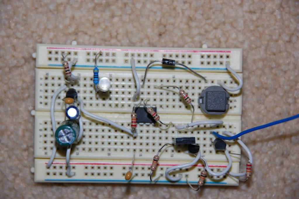 I got in contact with our good mate Murray who makes all the code readers for the e-series... He wrote a program and uploaded it into a PIC for me and bench tested it... I got it Friday and breadboarded it this arvo to bench test and real life test it... After one hiccup which we are not real sure why it happened... It now works good... Basically this replaces the 2 button "on/off" on the EA-AU with the 1 button arrangement used in the BA/BF/FG... Now my one on/off button will trigger the cruise on and then off... Characteristics being 100ms debounce, 750ms pulse time, built in interlocks, start up safety features... So holding the button for a long period will cause a 750ms pulse, pressing it for less will cause a 750ms pulse... It had to be pulsed because for the sense wire to work with the set- set+ and resume buttons the on/off button must trigger "on" and then go to a neutral state (neither +ve nor -ve)... For me to replicate this with basic IC's the would have been 4 times the components and a lot more nightmare... This circuit should turn out fairly small and will live where the airbag is... The three wires usually used in the E series cruise system will enter onto this board and then 3 more will run to the switches... basically this goes in the middle... No extra wires to be run or any of that nonsense... Being a PIC it is super accurate and reliable compared to doing it with basic IC's... Makes me wish I knew how to prgram these things... Chipping away at it anyway... Now to start drawing up the circuit board in the PCB designer I have and then route the tracks... Cheers, Tim
_________________ {DESCRIPTION} |
|||
| Top | |
|||
| TimmyA |
|
|||
|
Quick foresight after drawing it roughly up...
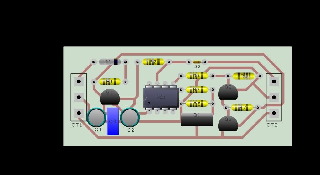 Should end up pretty small... Cheers, Tim
_________________ {DESCRIPTION} |
|||
| Top | |
|||
| Who is online |
|---|
Users browsing this forum: No registered users and 70 guests |