

|
| TimmyA |
|
|||
|
Received this PM
Quote: hi mate, been reading about your changing from a ba wheel to an fg one. im not much of an electronics person so i didnt quite understand alot about the switches. what im interested in is how hard it would be to go from fg to a ba wheel? i like the look and feel of the chunky ba/bf fpv wheel. good job on all your mods by the way, car is looking good... So will post in here as others may find this useful... Can be done... Parts you'll need is FG switches which you'll need to the cut the plug off to fit into the clock spring... BA switches you'll need to cut the plug off and fit the FG plug to... Other than the obvious wheel and airbag shouldn't need much... OK the basics... The FG wheel has a huge whole for the wires to come through... Most would have never seen how the clock spring works... But the 4 airbag wires are like normal... like 4 inches long and two wires go into each plug... the horn/cruise/radio buttons vary greatly... the plug for these is moulded into the clock spring... there is no dangly wires for these... The buttons plug into the clock spring itself... Hence the massive whole in the back of the FG wheel so accommodate this plug... First guess would be the BA wheel needs to be opened up to go over this moulded plug as the BA wheel has a tiny whole in it... Die grinder should make short work of it... BA: FG: 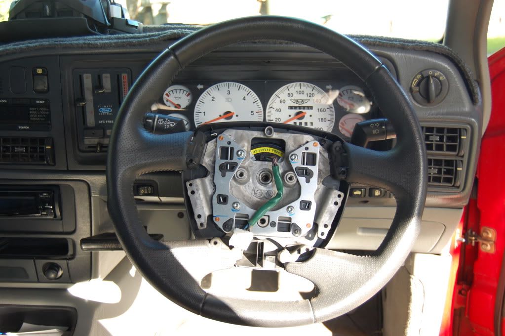 Next issue... When you plug into the clock spring you have a plug sticking into the back of the airbag along with wires which loop out and run sideways... The FG has accommodated space for this plug being here... The BA's plug was on the side of the airbag so didn't need space behind it for a plug... Only way you'll see if it fits is to fit the BA wheel, plug in the switches, and see if the airbag will sit all the way into the wheel without fouling on the plug... Can't help you there sorry... BA (no airbag): Last is the buttons... If you cut the BA plug off the BA buttons and solder on your FG plug and get the colours all hooked up right you'll have a working horn, a cruise system that should work (only one resistor varies very slightly) and a radio that doesn't... The resistors need to be pulled from the BA's board and changed to the FG values... One will need to be added (the first one (51.1ohms)) which the BA doesn't have provision for (not hard to add though)... And the phone button will be obviously lost... If you can't do this I can providing I can find resistors in non SMD in the SMD values they used (I can't work SMD components real well)... Also providing there is physically room (looks good in bellow picture) for the larger non SMD resistors... I had no trouble when I changed my cruise buttons though so shouldn't be overly hard... BA: 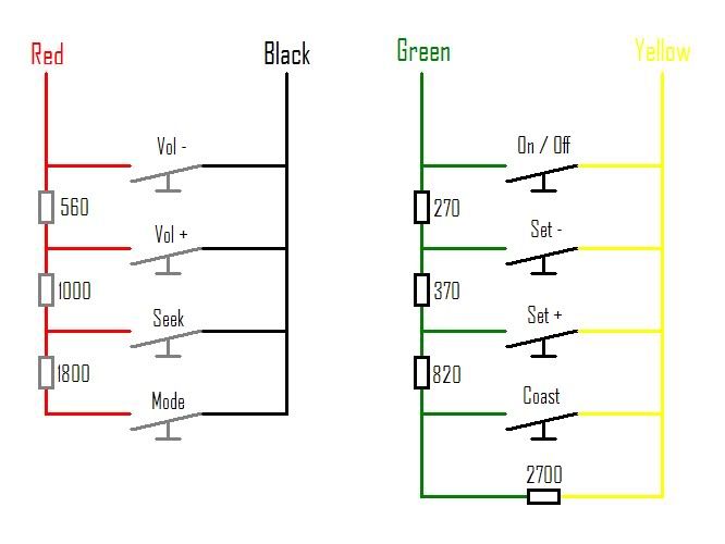 FG: 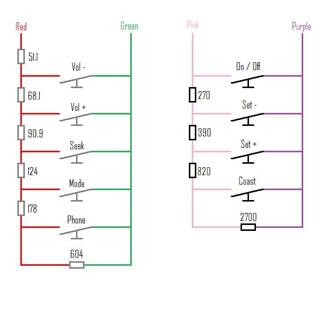 Only remaining thing you'll need to consider is whether the airbag changed... Obviously the two plugs may be different... Secondly the internal resistance may vary and throw flashing lights up at you... Thirdly the requirements to operate the bag may vary and may either not go off or may go off prematurely... So I only recommend using a BA airbag and trying to fit it to the FG hornpad somehow... Again I don't need airbags in an ED so I never look into this... BA Airbag: That'll get you started anyway... Cheers, Tim
_________________ {DESCRIPTION} |
|||
| Top | |
|||
| phatba |
|
||
|
hmmmm so it is a possibility then, but requires stuffing about. maybe i should wait for the warranty to expire then before doing that. whats the legalities regarding altering the steering wheel to fit and the plug changes for ba to fg?
|
||
| Top | |
||
| TimmyA |
|
|||
|
After being on here I have learnt with the right amount of money, skills, and mates in the know anything is indeed possible...
As always yes there is some stuffing around... Any modification is technically supposed to be engineered I think so yeah... Most of use take it with a grain of salt and do mods as safely and tastefully as possible without going stupid... Most things void warranty I guess... But you make the system plug and play so you simply unplug it and plug the FG back in as though it had never changed... Its not a big job... If you buy another set of cruise buttons (I seen a set on ebay for $25 buy it now not long ago)... Cut the plug off... Find BA buttons and chop the plug off... Hook the FG plug to the buttons... And if you can't change the resistors I can do it for you... The biggest law thing will be the airbag... And as I said I'd be dismantling a FG hornpad, pulling the bag out... Pulling a BA bag out and seeing if you can make your airbag fit with minimal mods to the hornpad... I want a FG hornpad... I need to remove the bag... If I find one (still looking) I'm more than happy to send you the bag (only will be sitting around like the BA one I removed)... then your hornpad stays complete... I can't see making that hole in the wheel bigger ruining its structure... The FG hole is over sized anyway from memory... Best just get the BA wheel and sit it there... Remove a bit... try again and keep taking it in small steps... That's some info for you to ponder anyway... Cheers, Tim
_________________ {DESCRIPTION} |
|||
| Top | |
|||
| TimmyA |
|
|||
|
Progress As Always! And a fair bit of it...
The end of the Long weekend result in fixing up some wiring in the car... There was a silly plug in the bottom of the fuse block next to header tank... I noticed when I put it in and it does both the thermofan and the ALB wire (which is power to charge the boot battery)... I could see this resulting a high resistance join so I got rid of the plug and hooked the wires in the same way as the rest of the fuse block was done... I pulled out the low beam timer as I was having minor issues occasionally with it acting up... Reverse the wiring back... Changed the patch harness under the dash and shorted two wires in it which the wire from headlight switch up to the combo and low beam wire from the combo to the relay... So basically the low beam relay is now locked on that way to suit the XR lights... As opposed to the bridge and the 5 pin relay which causes a rapid flicker when you change from high to low and low to high... Which is no good for HID lamps... Also last weekend the Wade 1636 went in... Checked the factory cam shaft timing before we pulled it out to get an idea what it measured at the Valve at TDC (no.6 firing)... There is no real spec for this, but the Ford Manual says no 1 intake should open at 16deg BTDC... My camshaft was open (at a guess) at like 5-10degrees ATDC... So that can't of helped much... Was shocked to find it so far out... But skimming the head... Stretch in timing chain all cause that to happen I'm told... Now my understanding is that the camshaft was retarded (being as though it opened late)... Now can anybody reading this tell me whether or not a retarded camshaft works up high or down low? I know retarding makes it work at one end more and advancing moves it other way (to a point)... When I re-installed the thermo hub when completed and took it for a burn around town the thing locked up and then wouldn't free up... When the lock up to full speed man do you know it... No engine performance at all and you'd swear a Boeing was taking off next to you So with that mod in went the EEC-V computer... In went the EL thermofans... In went the XH snorkel which were all sitting around waiting for the day... EEC-V computer is J3 chipped by Jason to suit the lumpy stick... I don't have a wideband and it hasn't been to the dyno but on all accounts seems nice to drive... Only issue is the J3 was programmed to idle at 850rpm which I only just found out Jason set it there... It is way too high for my liking... And the dashpot (which I only just discovered existed) is not right because it can take anywhere from 5 to 10 seconds before it drops all the way back down to 850rpm... Makes changing gears hard... But the high idle may be playing with the dashpot because I read it can do that... So next is to order a programmer and change it back... I can change these easy things... But I'm not really up with doing maps or anything... So if anyone can recommend one good piece of literature or website that made everything really easy to understand when programming I'd be keen to hear about it... Jason reckons all the info is on his website but I can only find dribs and drabs and it is all over the place... Also anybody who programs their own J3 chips I'd be keen to talk to you about a couple of EEC specific things... Thermofans need modding as all know... the tab on the bottom hose needs a bit cut off it to make them sit down far enough to get the top bolt in... Good news is you can run thermos on the 3 belt set up... Water pump misses them by half an inch or so... Win win there as I'm not a fan of the serp belt idea... Only thing left here is to get me an EF/EL upper housing and hose... The ED misses when their in but you need to flex it to get them past... Bit of a hassle... No photos of this yet but will follow... Today I had great intentions to progress on the FG wheel a tad... And then start planning some works on my house... Got the FG wheel stuff done then got visiting... So now the house has been moved back a bit... Soldered up the new cruise switches with the resistors to operate the EL cruise module... And soldered in the 5th button which will scroll the ODO in the NL cluster when it goes in shortly... 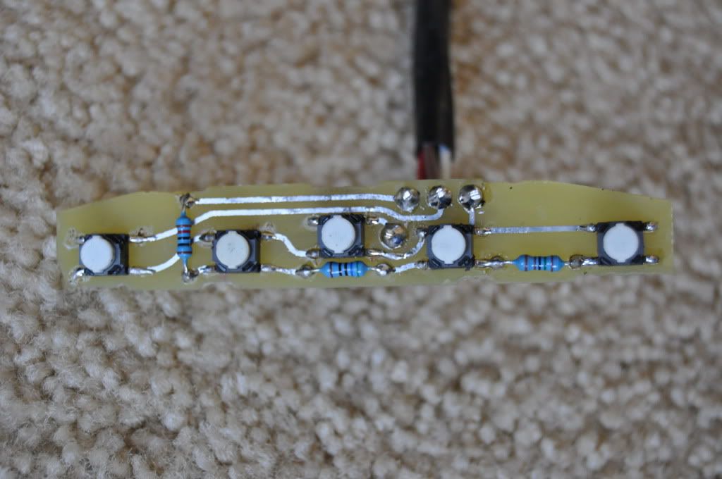 And the alignment of the buttons once inside the housing (helps to have a bother who knows the ins and outs of photoshop and the time to spend a whole Saturday re-creating the switches and add tracks to suit me 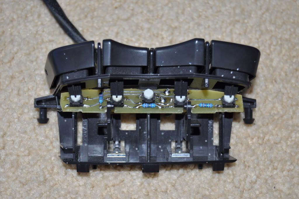 Also the on/off adaptor circuit is made up and ready to be solder in line once I have an airbag and know how long the lead from the switches to the module need to be... 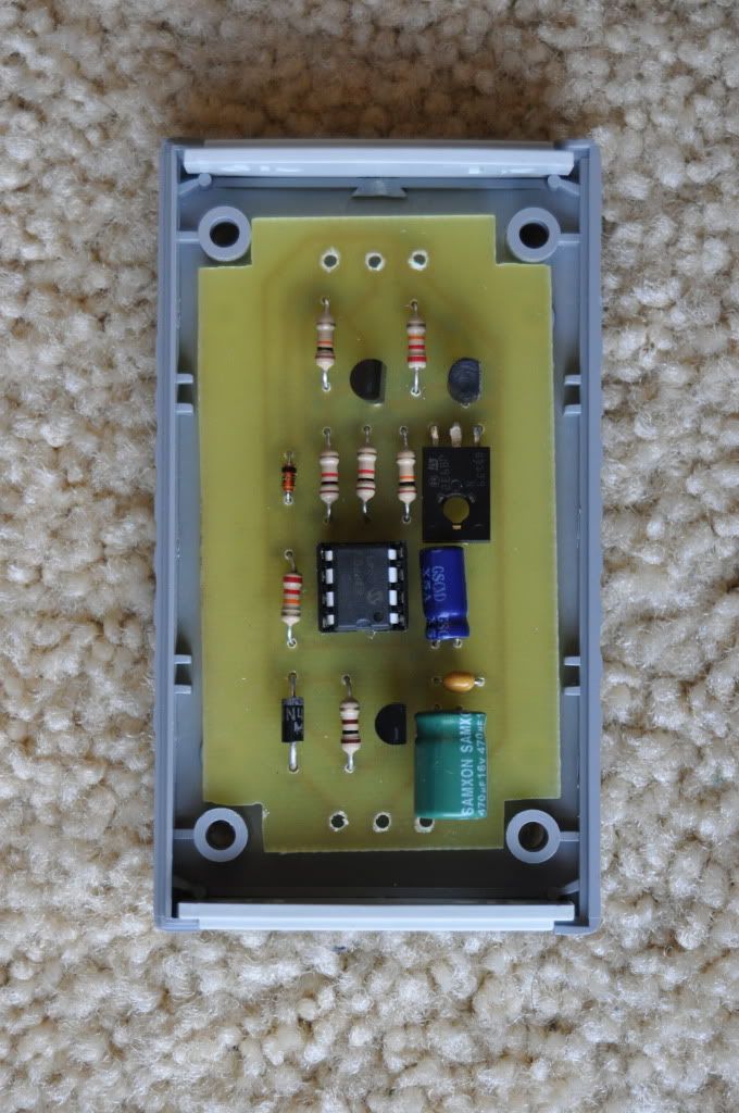 So a lot has been achieved of recent... Couple more things to do... Finish of the parts of the wheel and put it back together... Chipping away... As for now... It is off to learn about irrigations systems so my lawn can learn to water itself... Cheers, Tim
_________________ {DESCRIPTION} |
|||
| Top | |
|||
| Matt_jew |
|
||
|
As always Tim nice progress being made!
_________________ {USERNAME} wrote: More people paid for a ride in a VT commodore then an AU Falcon so the VT is superior.
Based on that fact my Mum is the best around! |
||
| Top | |
||
| TimmyA |
|
|||
|
Always tinkering with something Matt...
If I'm not trying to be productive then I'm in trouble for annoying somebody... Cheers, Tim
_________________ {DESCRIPTION} |
|||
| Top | |
|||
| TimmyA |
|
|||
|
Advances this weekend is I am now running an EL 3.45 LSD diff...
Lokka is gone now... So much nicer to drive... Can actually go around a corner now without having to clutch it... And no more noise... I couldn't count how many people have pulled me up and told me the a** end is about to fall out of my car... Wasn't too bad a task... The ED lines, where the "T" is on the diff, missed the EL breather by about 3 inches so I welded a bolt to the diff and bolted the T there... Weld three tabs on in the same spots as where the ED has them and folded them over the lines, The passenger side line need to be re-shaped a tad to miss the breather... Kitted the rear calipers... Gave them some Brembo red too... Looks good... The caliper brackets got a hit with the acid and the alloy looks like brand new... Backing plates are as black as black can be after a good clean... Incredible looking a** end now... If only you could see it... So if anyone wants a Lokka there will be one for sale sooner or later... They're a great idea... Just not for me I think... Quite happy with an LSD for my use thanks... 3.45 over 3.27 seems to have made a tiny tiny improvement to the torque off the line... And with me guessing what "feels" like 50 km/hr when I look down I'm doing 58 so will check that with the gps and then fit the 22 tooth gear and see if make much improvement... Other achievements is the completion of the NL cluster loom... So it is finished... Just gotta put some resistors in the door ajar one so it stops flashing at me... Got the LCD to illuminate now.... And just gotta change out the oil pressure sender... Will fit it up again tomorrow and put some LED's in it and see how it goes at night... I'll get some white faced dials made up for it too once I sort out what it is that I want... Programmer turned up for my J3 chip... Knocked the idle down from 850 to 700 and tripled the dashpot figures... Again much nicer to drive now with those figures adjusted... Fairly happy driver for now... Will get some picks of the NL cluster loom tomorrow and some of the FG wheel I'm slowly making up too... Cheers, Tim
_________________ {DESCRIPTION} |
|||
| Top | |
|||
| BOSXR8 |
|
|||
|
Progressing well. I had a locker in my XE and for a cruiser that I drove once a month if that I still found it annoying, can't imagine what it would be like to drive daily. Some people love them though.
_________________ EB SXR6. ED XR8 Sprint. |
|||
| Top | |
|||
| TimmyA |
|
|||
|
Always mate...
Got the NL cluster in now... Perhaps BenJ can fill me in if he reads this? Ben mate, you may or may not have experienced this with the NL cluster into an ED... The trip computer told me I had no juice and a bit later the light came on in the cluster as per normal... Filled up and then started the car and the trip computer still told me I'm empty? It is as though the NL cluster ruins the sender resistance and then the poor trip computer loose its s**t... And continually notifies me of having no fuel... I am keen to get the EL trip computer into the ED now... after probing around tonight I think it may be possible and once I make up a matrix chart of cross over parts and am sure I can make it happen I'll post up more details of the concept... And other advances to happen it that damn bracket I made up... Couldn't for the love me get it to fit last night... So I'll welding some webbing in and removing some of the mass that hangs out the sides... I chopped a whole heap of unnecessary protrusions off and got it to just fit... This is the patch harness... 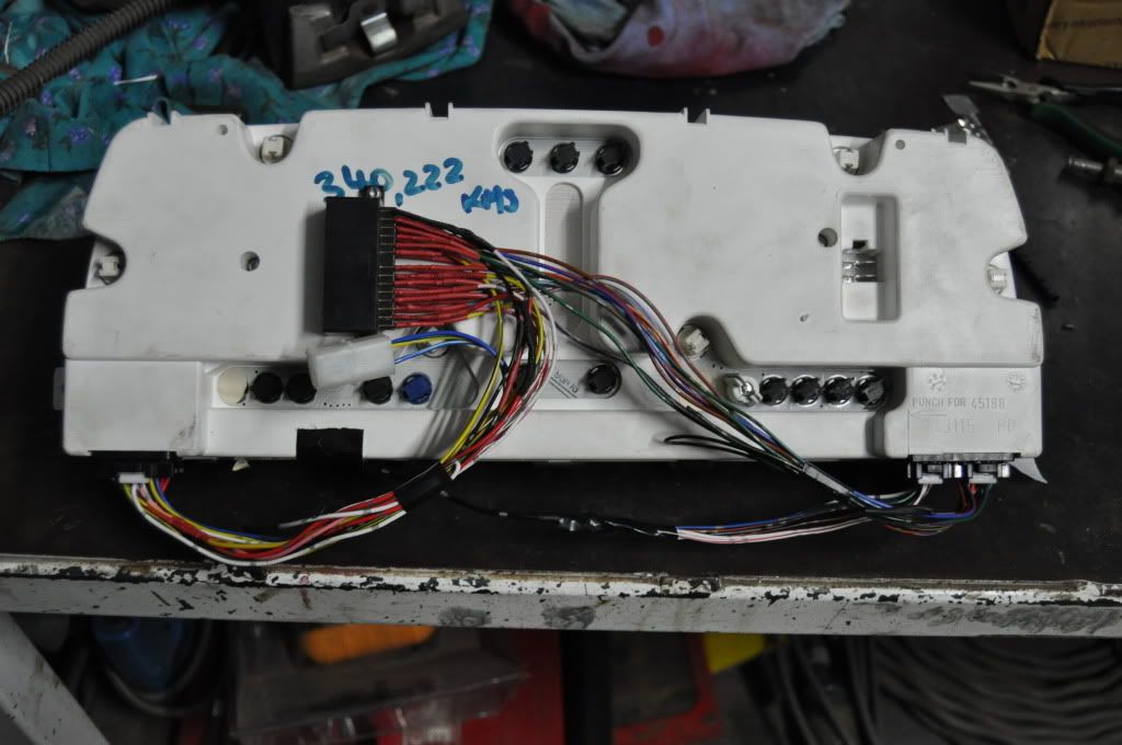 For now the door ajar stuff is just bridged out... Not sure if I'll even bother with it... Thats me for now...
_________________ {DESCRIPTION} |
|||
| Top | |
|||
| TimmyA |
|
|||
|
OK difficulties encountered with the trip computer conversion already... Resulted in a burnt pinkie finger...
So emailed VDO Been thinking about what style gauges to get this time round... Don't mind the look of the these: 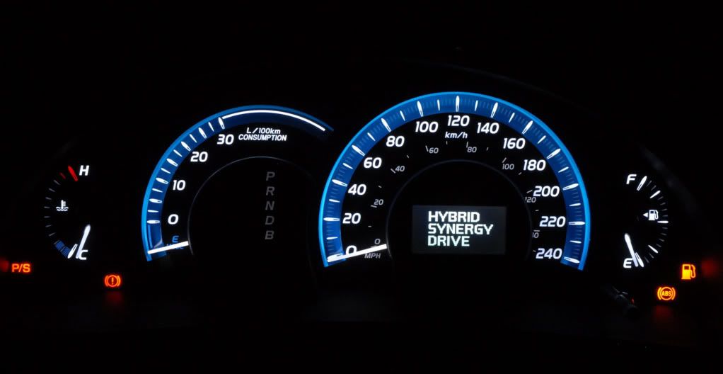 And these two are OK too... 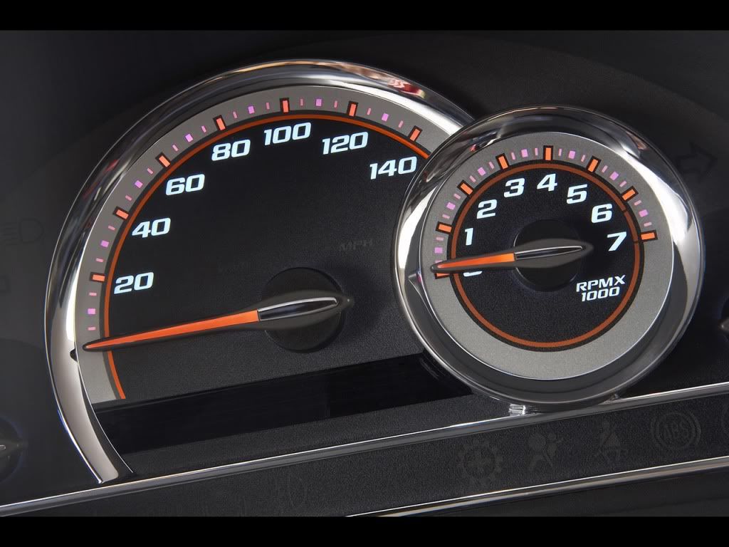 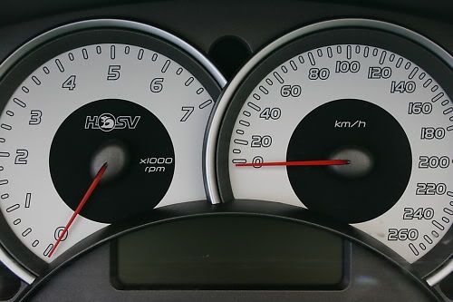 Not sure what I'll end up with as yet... Whether it'll be a mix of these or something different... The white faces thing has gotten a bit old and I like white illuminated numbers now... Changed the rest of the interior to white except the headunit which is either blue or red... Everyone has blue these days and it's a bit of a tired look nowadays... So maybe a little bit of blue as above and white numbers and maybe red needles... On that note can I put any EF/EL red needles into an NL cluster? Cheers, Tim
_________________ {DESCRIPTION} |
|||
| Top | |
|||
| BenJ |
|
||
|
Hi Tim
Trip Comp I gave up trying to get the EA-ED trip comp working correctly with the EL ECU as the trip comp uses a different source from the ECU. The EL Trip Comp and the EF/EL/NF/NL cluster NEED the data line as supplied by the EL ECU to function correctly. If you can get it to work then good on you. I ended up doing the whole dash conversion LOL. NL Cluster Needles The needles on the NF/NL cluster are the same, but are different from the Low and Mid versions. While you can use the orange EL needles they look different, and are not as nice in their design. I have played with the idea of adding some sort of colour to my NL needles, and even have a spare set to mod, so they light up Red at night but look white during the day. Custom Face Design I did have custom faces on my EB cluster, but have not had a look at doing them for the NF cluster. The designs you are looking at are awesome, but you will need to pull them off well, which is harder than it sounds. Looking forward to seeing your efforts. Cheers BenJ
_________________ {DESCRIPTION} - Current Ride |
||
| Top | |
||
| Smiffpig |
|
|||
|
I just flicked through the whole build and can i say no other build has made me want an ED as much as yours does, keep up the amazing work !
|
|||
| Top | |
|||
| TimmyA |
|
|||
|
G'day Lads,
Firstly: {USERNAME} wrote: I just flicked through the whole build and can i say no other build has made me want an ED as much as yours does, keep up the amazing work ! Cheers mate... Good to know I attract some interest from new comers and non followers... Fear not though mate... I do love this car... OK... Rather handy sort of weekend... Cleaned up the old mans shed and put a bunch of things back together I have had pulled apart for months to fix up and never got around to it... So I put a recipro saw back together that had a bearing flogged out I had to shim up... And a ducted vac system motor that was "burnt out"... Ended up chewing one brush away and the braid inside hit the commutator and scored it... So cleaned it all up and polished the commutator down and got some new brushes and it is a as new spare for my old man now... Plus as I said a general clean and there is now miles of room I didn't know we had... Other accomplishments involve helping a mate out with his hilux which kept blowing a instrument cluster fuse... It is one of those things we fixed but darned if we know how we did it... :/ It was blowing 10amp fuses but after wiggling looms and probing around it now draws 0.34 amps and seems happy... Plus fixed a couple of other minor things... Today I installed my new speedo drive gear... Cheers to Ash... I compared it to the GPS before and it was roughly 10% out (111km/hr on the speedo was 100km/her on the GPS)... So this means I need and extra 10% teeth on the drive gear in theory... I have a manual 6cyl with a 3.27 factory diff... The speedo calc page is not very clear for an ED... But I do indeed have a light green 21tooth gear... So 10% on that is 2.1 teeth and that gives me 23.1 teeth... That may be a little hard to find... So I guess I'll have to settle for a 23 tooth... I did fit the grey 22 tooth gear and I'll test it out but I think I will need the black from guesses alike... Time will tell... I think the old man have a black one at work... If not I may need your help again Ash... Also... ANNOUNCEMENT! We have the new "slimline" NL cluster bracket that fits into the dash with 1/100th time less cursing and swearing than the previous model... 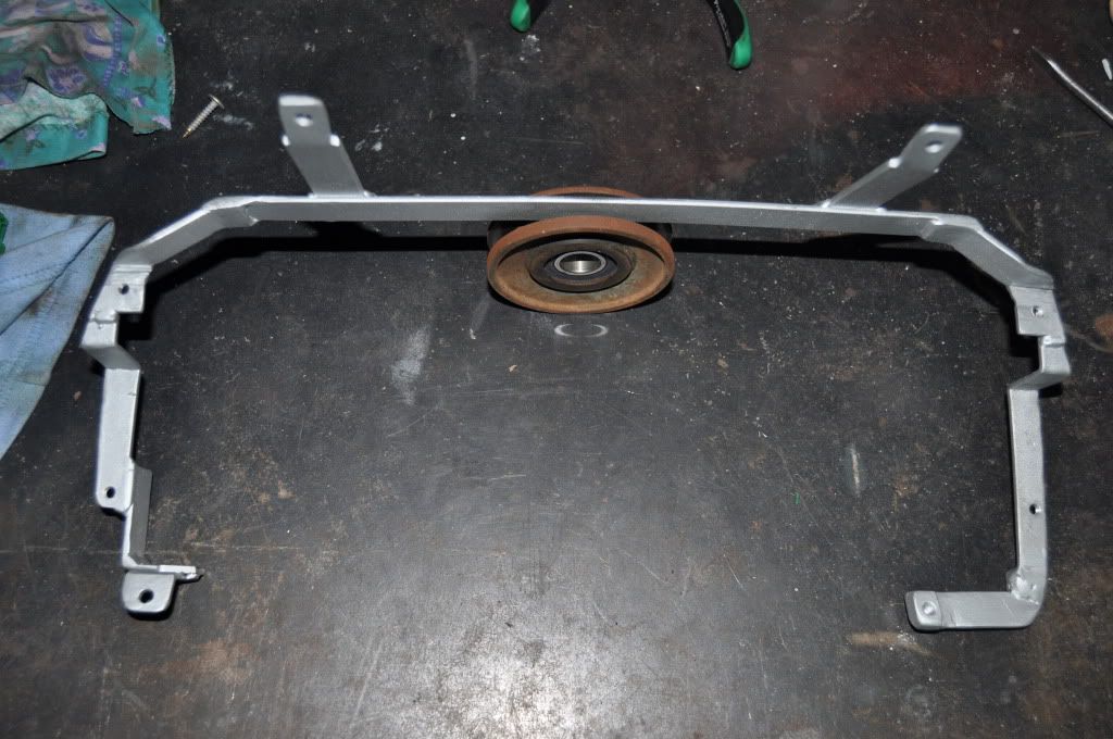 Improvements include bringing in the top corners closer to the cluster... trimming 5mm or so off the sides... Cutting out the bottom brace... Cutting off all protruding pointless parts... And re-designing bottom right mount... Top corner design: 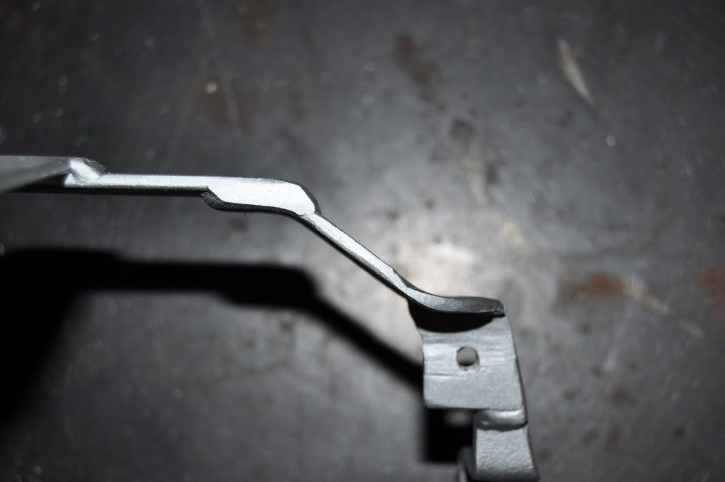 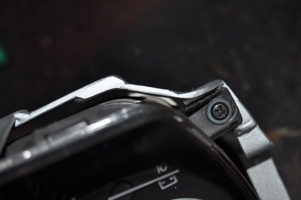 And bottom right mount: 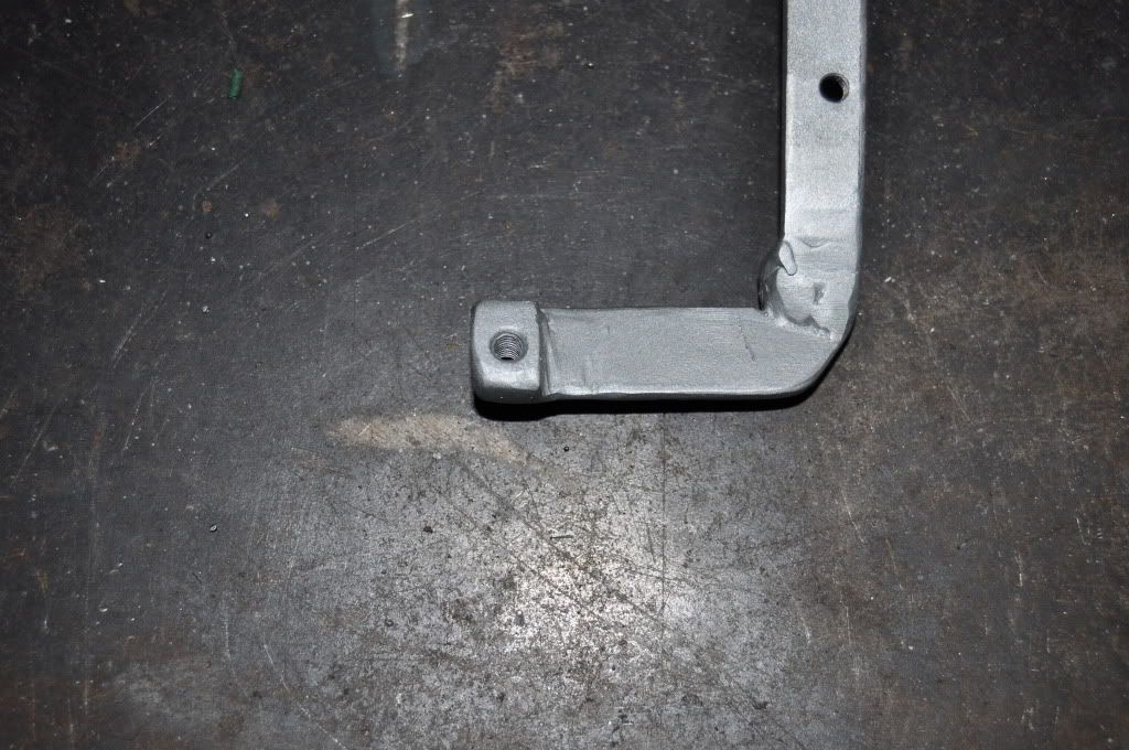 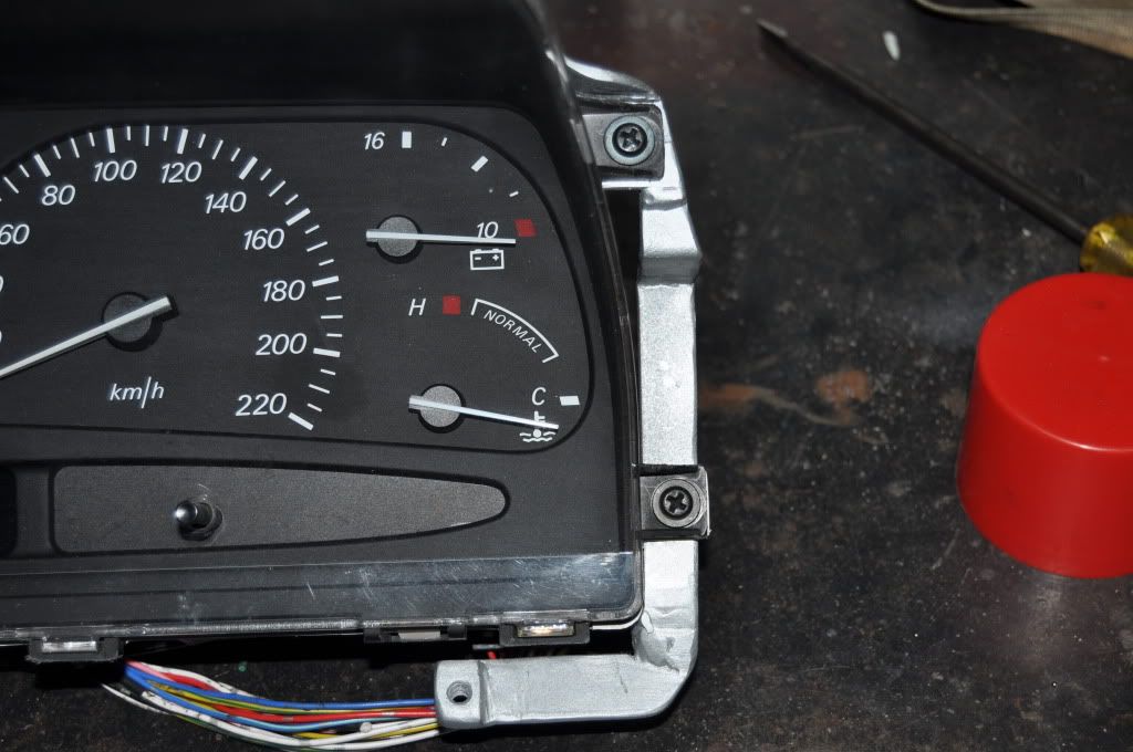 This corner changed in the sense that I removed the speed nut and this sits behind the plastic and is threaded... This gave me more clearance with the wiring to get it though and also means I don't have to lift this corner over the dash section to get it back in front as this bracket is inserted with this corner behind and getting it in front was the hard part... Modding it was easy coz I could simply weld the new part in and cut the old part off meaning all the alignments I had are now unchanged... Made up one good cluster out of my two I have here... but not really happy with the gauge behavior of these ones so i may pull it back out and swap the gauges back (about 5% difference between digital and analogue speedo and tach jumps to 1000rpm when you switch the car off and drops to 600odd and then just sits there... with the car completely off... Still planning the ED/EL trip computer hybrid presently... VDO haven't emailed back so unsure whether they'll help or not... I may actually have to do some hard yard with this one... If some electronics engineer happens to read this... With an LCD screen such as the one in the trip computer... What do I need to drive the segements? Are they like an LED? 12Volts with a current limiting resistor? Drop it down to 20 or 30mA? Just don't want to burn out the LCD is all... Sooner ask before I probe around in the dark... Last but not least the FG wheel is pretty much done as much as possible until I can get my hands on an airbag to make final wiring measurements and solder the buttons to the plug... Cheers, Tim
_________________ {DESCRIPTION} |
|||
| Top | |
|||
| TimmyA |
|
|||
|
Yeah mate... Didn't achieve an awful lot... But having space on the work bench and floor space feels like a big plus...
Yeah I'll drag the GPS back out tomorrow and check it... I think I'll put the other speedo set in this NL board because it seems more accurate than this speedo... I'll swap it first and see if I can make the digital and analogue closer reading wise... Then I'll compare to the GPS and post the findings... Was suprised just how easy that job was though... Couple of tools... 15 mins... Pulled out, swapped, cleaned and put back together... Cheers, Tim
_________________ {DESCRIPTION} |
|||
| Top | |
|||
| TimmyA |
|
|||
|
Been flat out like a lizard drinking lately... Installing solar systems currently and just about had enough of them for the next 10 years I think...
None the less thoughts have been ticking over in my mind... Still on the trip computer issue I am having... For those unaware... The trip computer tells me I have 60km to empty everytime I start the car and will slowly rise up to normal over a period of time... It is annoying because it beeps at you when it gets to 80km or under... Only happened since the NF/NL cluster went in so that would leave one to believe it caused the problem... Tried two things already... One was to fit the entire EL screen and buttons into the ED hosuing to clip into my dash... That was to hard to make and would involve me being a plastics genius to make a new front housing to include mounting point to screw it into... The EL screen uses those silly rubber connector thingos instead of just metal pins like the ED so you can't just solder it to a board you etch up it has to be sandwiched to it... So the hard part it finding a way to sandwich it... Tried various things and eventually put the idea in the two hard basket... Second method was to use the front board as the per the std T/C... with the ED screen solder to it and power it with the EL board and this would have made buttons and illuminate simple as I could work the same as the ED one... Turns out EL LCD has 4 more pins than the ED one... No big deal I say... 2 have no tracks on the board and hence not used... And I would guess one of the remain two does the speed alert symbol (which I wouldn't use anyhow)... So I got me a 40 core cable and solder it to all the terminals on the EL T/C board and then plugged the ED LCD into a breadboard the other 40 ends into the respective pins on the LCD... Turned out not to work... The ED LCD is not multiplexed because the LCD driver chip has two blackplane pins but only one is used... Now the issue I have is identifying the EL LCD driver chip... This chip was specially built for VDO by NEC... The numbers on it mean nothing to NEC and they said I had to contact VDO who never replied to my emails... SO dead end there... Unless I can find which find which pin (guessing it isn't multiplexed) is the backplane the possibilities for the combination of pin arrangements is quite large... If my maths is correct this is solved by the equation 40! which is 8.16x10^47 possibilities to work out every pin if worst came to work... If I knew the backplane pin it would be heaps simpler because I'd have a fair idea then... As such this idea has too been put on hold... Todays brain storm was that one of two things may fix it... First one being that: Now the fuel sender is a variable resistor hooked to earth (from memory and not to 12V)... so what would cause the T/C to get confused? It never changed and is still there... Maybe the cluster is a really low resistance circuit and the T/C is picking up through both the cluster and the sender (as resistors in parallel)... Maybe the cluster puts too much voltage onto the sender wire to measure the current and as such it is feeding voltage into the T/C and it is causing miss-readings... So I am thinking two diodes in the sender circuit with the cathodes hooked to the sender and one anode to the T/C and one to the cluster so they cannot feed into each other or see each other... Maybe this will work? Other idea is to find me a fuel pump assembly and see whether another sender can be attached under the lid to work off the one floaty arm... The use one for the T/C and one for the cluster... Make them completely separate? This way I retain the ED T/C as a complete and functioning unit... Bother of these require that the T/C will work as a stand alone without needing to the cluster resistance... If the cluster resistance in the ED cluster then I'll need to measure it and hook in a resistor to create a voltage divider if it works in that fashion which may very well be the case yet... At this stage thought I'm leaving the hybrid T/C idea for a while and looking to actually fix what ever caused the problem as opposed to just stick EL gear into it... Thoughts lads? (Those who aren't confused anyway)... Cheers, Tim
_________________ {DESCRIPTION} |
|||
| Top | |
|||
| Who is online |
|---|
Users browsing this forum: No registered users and 39 guests |